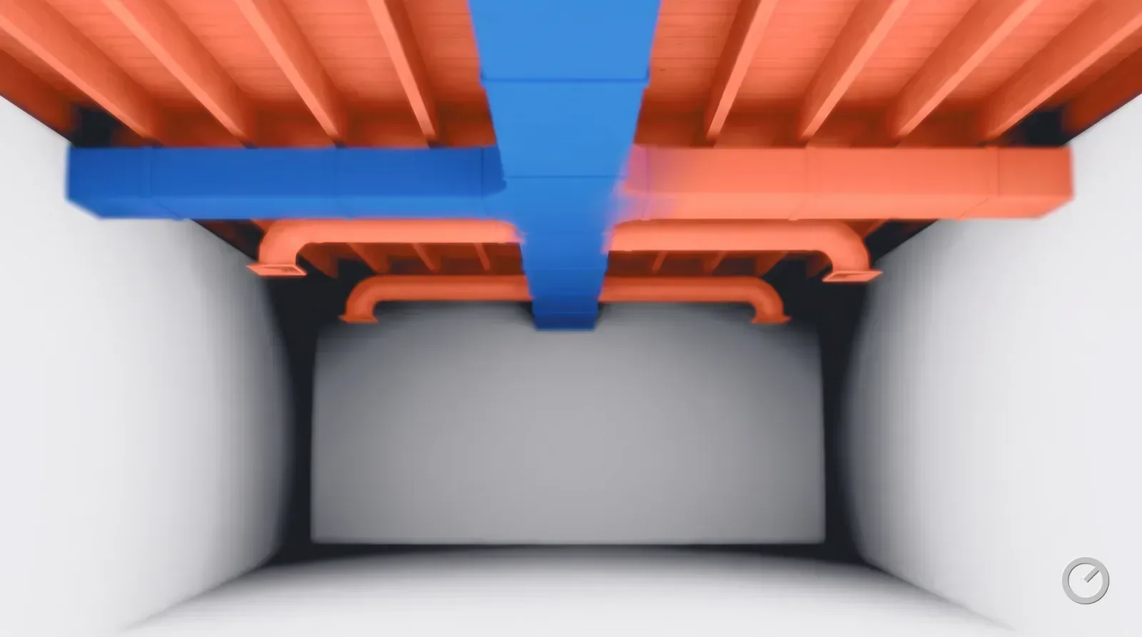
Step 1 — the airflow
Cooling equipment wants 350 to 400 CFM per ton — 400 in a dry climate, 350 where latent load matters and you want the coil colder. A three-ton system at 400 CFM/ton moves 1,200 CFM total. Distribute that room by room in proportion to each room's share of the cooling load, not its floor area.
On the heating side the airflow comes from the furnace's temperature rise range instead: CFM = output BTU/h ÷ (1.08 × rise). Size the duct to whichever airflow is larger, which in most houses is the cooling number.
Step 2 — the friction rate
Available static pressure divided by total effective length, times 100. Start from the blower's rated external static pressure — usually 0.5 in. w.c. on residential equipment — and subtract everything that is not duct: the coil, the filter, a humidifier, balancing dampers, a grille with a tight free area. That subtraction is not a house rule: the design figure is defined as the pressure at design airflow inclusive of the evaporator coil, a whole-house humidifier and a MERV 6 or better filter, so anything on that list which is worse than the design assumed comes straight out of the duct budget.
This is where designs go wrong
A 0.5 in. w.c. blower with a 0.22 coil and a 0.18 filter has 0.10 in. w.c. left for the entire duct system. Designing at 0.08 in. w.c. per 100 ft with 150 equivalent feet of path needs 0.12 — more than exists. Either the filter gets deeper or the ducts get bigger; assuming it will be fine is how a system ends up at 0.9 in. w.c. of static.
The static pressure calculator does the subtraction and the division for you, from readings you take with a manometer.
Sources: EPA ENERGY STAR, National HVAC Design Report v3.1/3.2/3.3 (Rev. 14, revised 2025-01-15), Item 5.1 (read 2026-09-04)
Step 3 — total effective length
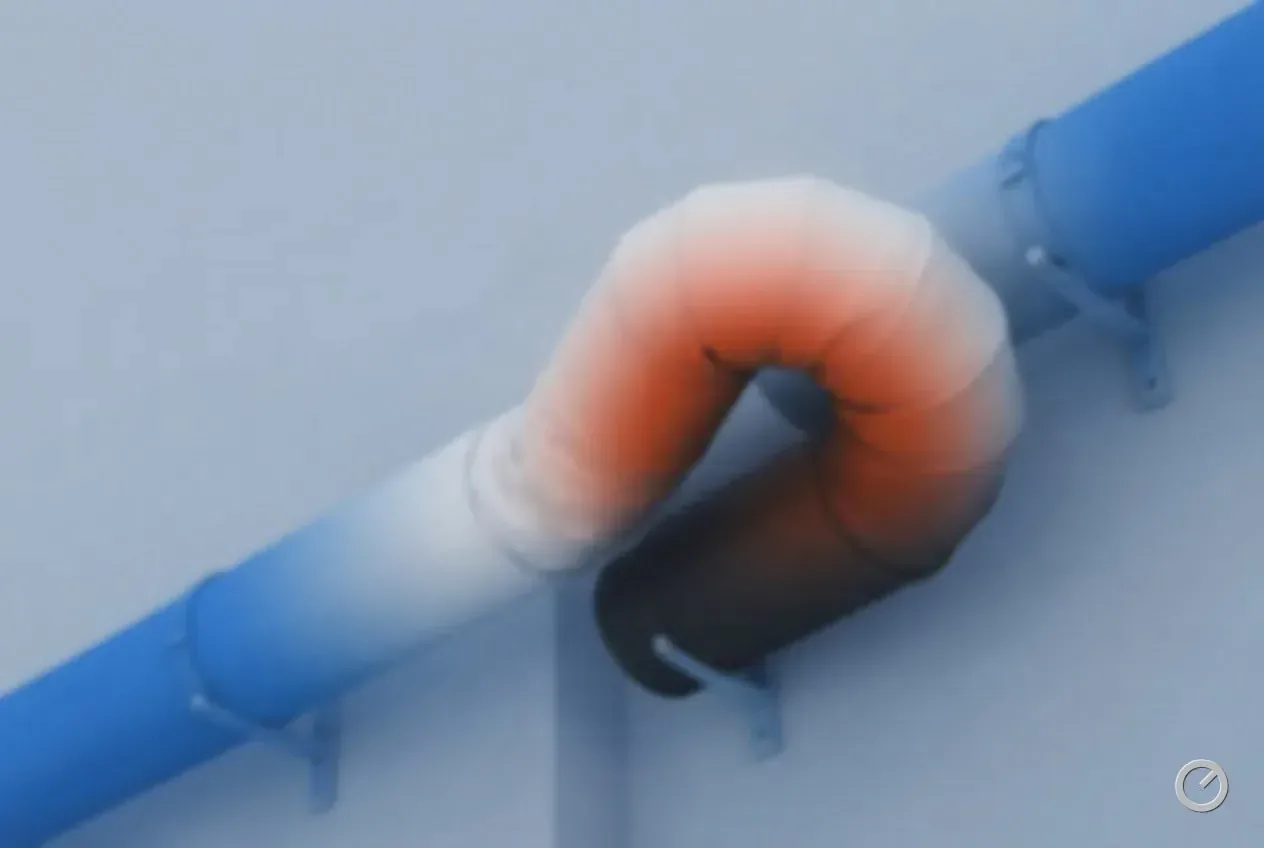
Not the tape-measure length. Total effective length is the longest supply path plus the longest return path, with every fitting converted to the equivalent feet of straight duct that would cost the same pressure. A boot is worth tens of feet. The published figure for a proper-radius 90 in flex is 15 equivalent feet at 700 feet per minute — and that is the number for flex installed correctly. Kinked, bent tighter than one duct diameter, or squeezed into a cavity narrower than the duct, it is worth far more, which is exactly why installation quality is a duct-sizing input and not a finishing detail.
| Fitting | Equivalent feet |
|---|---|
| Smooth 90° elbow, round | 15–25 |
| Straight take-off from a trunk | 35 |
| 45° take-off (conical or bell) | 10–20 |
| Supply boot to a floor register | 35–60 |
| Return grille and boot | 35–70 |
| Flex 90° bend, proper radius, at 700 fpm | 15 |
| Trunk end cap take-off | 50 |
The flex row is the published figure; the rest are screening values. ACCA Manual D, Third Edition, Appendix 3 carries the authoritative tables by fitting geometry.
Sources: DOE Building America Solution Center, No Kinks or Sharp Bends in Flex Duct Installation (read 2026-09-04) · EPA ENERGY STAR, National Rater Field Checklist v3.1/3.2/3.3 (Rev. 14, revised 2025-01-15), Item 6.1 and Footnote 24 (read 2026-09-04)
Step 4 — the sizes
With airflow and friction rate in hand the sizes are arithmetic — the duct size calculator solves it directly. Two checks after the number comes out. First, velocity: over about 700 feet per minute in a branch and you will hear the register; over 900 in a trunk and the whole system whistles. Second, flex: if the run is flexible duct, either go up a nominal size or design it at a friction rate about 25% lower.
Returns are half the system
The return side is where most residential duct systems fail. A single central return on a house with closed bedroom doors cannot bring air back, so the bedrooms pressurise, the hallway goes negative, and the blower fights both. Size returns to the same airflow as the supply, and either put a return in every closed room or cut transfer grilles or jumper ducts so the air has a legal path back.
A quick field test: close all the interior doors with the fan running and measure the pressure difference between a bedroom and the hallway. The federal new-homes programme draws the line at ±3 Pa against the main body of the house — past that, the room needs a transfer grille, a jump duct or a return of its own. A bedroom whose design airflow is 150 CFM or more is allowed ±5 Pa instead.
Sources: EPA ENERGY STAR, National Rater Field Checklist v3.1/3.2/3.3 (Rev. 14, revised 2025-01-15), Item 6.2 and Footnote 25 (read 2026-09-04)